Overview
The following technical support notification provides a checklist and guidance for use when performing an annual check on Red Jacket Submersible Turbine Pumps. Only certified contractors should install or service Veeder-Root products.
Introduction
If annual checks are required, please follow the Red Jacket Annual Checklist and guidance below:
Visual Checks:
- Check for Fuel Leakage in STP Sump
- Check condition of Electrical Supply Cable & Cable Gland
- Check for corrosion of Packer Manifold, Riser, Line Leak Detect Valve or Transducer
Pressure & Flow Checks:
- Check STP Pressure with No Flow
- Check Flow Rate at Nozzle
Electrical Check:
- Current Drawn
- Supply Voltage
- Winding Resistance / Isolation
- Contactor Condition
Check for Fuel Leakage in STP Sump
Note 1. Leakage Checks
- Observe for leakage from external pressure seals, especially on STP integral check valve, and line leak detector port.
- Check for a tight seal at both ends of the riser to ensure air and water will not leak into the system.
- Check tightness of the integral check valve fixing screws.
- Inspect the integrity and condition of all fittings attached to the STP Packer Manifold, such as siphon tubes and fittings, and leak detection equipment tubing and fittings.
- Kinked, missing, corroded, or damaged fittings or tubing should be repaired or replaced.
Check Condition of Electrical Supply Cable & Cable Gland
Note 2. Supply Cable Checks
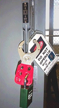
- Isolate the electrical supply to the STP and use Lock-Out and Tag-Out devices to prevent the supply being turned on by mistake.
- Check that electrical conduits and junction boxes are NOT broken or corroded.
WARNING: In older systems cables and cable glands may have been used as earthing points. Glands that are corroded or broken will not serve as an earthing path. If no ground wire is connected to the ground lug inside the Contractor Box, and run to the electrical panel inside the building, a dangerous condition exists.
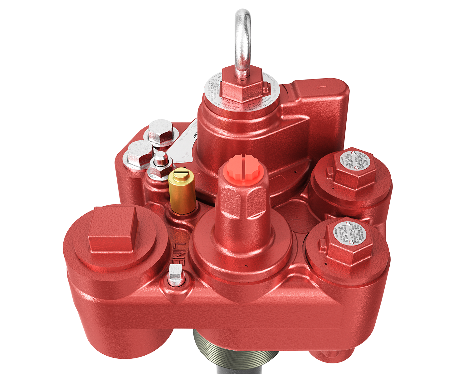
Check for Corrosion of Packer Manifold, Riser, Line Leak Detect Valve or Transducer
Note 3. Corrosion Checks
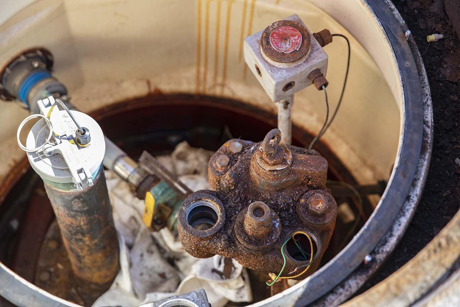
- Observe for good, non-corroded, O-ring sealing surface around yoke. Observe the condition of fasteners on the packer/manifold. Replace corroded fasteners, especially those on parts that contain fuel under pressure.
- Severely corroded parts should be replaced. Water entry into electrical junction boxes and product leakage may result.
- The current Red Jacket STP model, and some older models are fitted with a yoke, which when raised, isolates the electrical supply to the motor. Where fitted, undo yoke retaining screw to lift yoke clear of the Packer Manifold and break the electrical connection.
- Check to see that the yoke securing screw is tight and that the threads in the yoke body have not been stripped. Replace if they are stripped.
Check STP Pressure with No Flow
Note 4. Pressure Checks
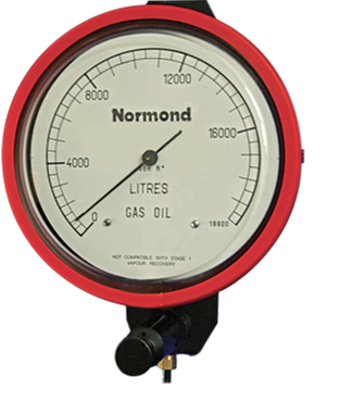
- Observe the pressure in the piping system with the pump running and no dispensing occurring. The pressure should be in the range shown in the pump manual. (Note that the pressures will vary with the product level in the tank.)
- Refer to UMP Model number located on order and locate specific UMP:
Standard Pump, Manual 042-153 Rev. T
Table 7 –Approximate Pressures at shut-off, page 29
The Red Jacket Pump, Manual 577013-830 Rev. AA
Table 6 –Approximate Pump Shut Off Pressures, page 12
Check Flow Rate at Nozzle
Note 5. Flow Checks

Check the flow rate at the dispenser nozzles to make sure that the dispenser filters are clean and there are no other obstructions in the system.
Check the Current Drawn
Note 6. Current Checks

- Observe the current drawn by the STP while it is running at shut-off pressure. Compare to the max amp value in the Pump Instruction manual. The value should be below the max amps value. The max amp value should only occur when the pump is delivering high flow rates.
- Refer to UMP Model number located on order and locate specific UMP: See the Manual Reference Notes below.
Supply Voltage
Note 7. Supply Voltage Checks
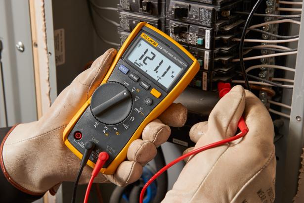
- Check the supply voltage on the outgoing side of the contactor, (at the electrical panel–not at the STP) with the STP running.
- High or low voltages can be detrimental to the STP motor life.
- Refer to UMP Model number located on order and locate specific UMP: See the Manual Reference Notes below.
Compare Winding Resistance & Isolation
Note 8. Winding Resistance & Isolation Checks
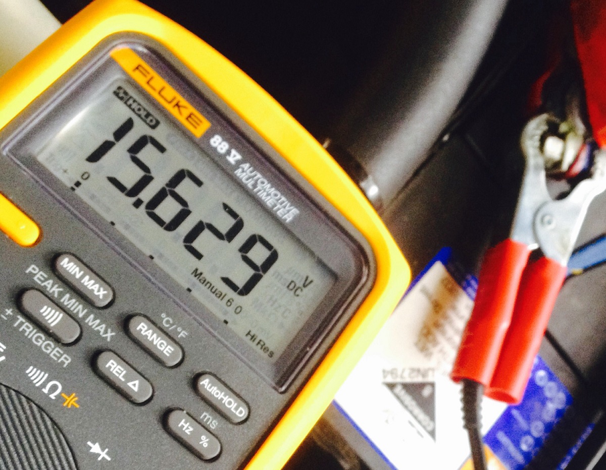
- Using a multimeter, check the resistance of each motor winding. Compare them to the resistance values in the electrical section of the Pump Installation Manual.
- Investigate if incorrect.
- Check the resistance of the motor wires to ground. The resistance must be infinite. A resistance path between a phase and ground can result in personal injury.
- Earth wires must be grounded at Earth Bus in main panel.
- Refer to UMP Model number located on order and locate specific UMP: See the Manual Reference Notes below.
Contactor Condition
Note 9. Electrical Contactor Checks
- Observe the condition of the contactor contacts as the pump is turned off and on. Replace the contactor if severe arcing or chatter is observed.
- Chattering may be the result of a faulty contactor coil or low control voltage from a dispenser run switch.
- The variability of specific voltages can cause chattering. If 3rd party contactors are used, these different manufacturers have different tensions on springs and allow for this low voltage range, causing chattering.
Source: Veeder webpage